17
Oct
2012

The audio world is overflowing with broad and deeply felt
generalizations (religions?) about tubes, designer capacitors, inductors,
and resistors, bi-wiring, cables, metal drivers vs. paper drivers–not to mention the whole digital vs. analog thing. Few of these beliefs are rigorously substantiated, and many can max out your credit card very quickly.
But there is one generalization that can be substantiated, and believing it
won’t necessarily destroy your credit rating. And that would be: “No
matter how much money you throw at drivers, components, and cabinets,
you can’t hide the effects of a poorly designed crossover.” Here’s a
corollary: “A speaker with ordinary drivers and an extraordinary
crossover will sound better than extraordinary drivers mated to a
so-so crossover just about every time.” If you’ve ever visited an
upscale audio dealer and listened to megabuck speakers that didn’t sound
that great, chances are the problem was inside on the crossover board.
crossover – why we need one
Before I go any further, let’s back up and examine why we need to be
bothered with crossovers at all. In a more perfect world, we wouldn’t
and shouldn’t bother. We would simply find a near-massless pulsating
sphere that would radiate full-frequency sound evenly in every direction
and be done with it. But at the moment and on this planet, the only way
to get adequate bass response is to resort large mechanical contraptions
(woofers) that flex, ring, and beam at higher frequencies, and the only
way to get clean, well dispersed high frequencies is with much smaller
contraptions (tweeters) that can’t displace enough air to produce bass,
and that would burn up if we made them try.
let’s build one
Let’s look at two reasonably high quality drivers-a 6.5″ paper midwoofer
and a ¾” fabric dome tweeter, both from Scandinavia-and see what happens
if we just throw them in a typical bookshelf size box (19″ H X 8″ W).
Here’s the response curve for the woofer operating by itself with
nothing between it and the input signal, which in this case is a very
fast sweep tone that shows how loudly the woofer plays at each frequency
between 20 Hz and 20,000 Hz.
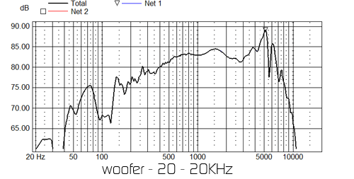
It is not exactly a straight line. To understand why the response
suddenly starts to increase at around 400 Hz before leveling off at
about 1200 Hz, see Jim’s excellent blog about the baffle step.
(Don’t even try to understand all of the peaks and dips below 200 Hz. At
that point the measurement software is capturing the effects of room
reflections and cancellations.) As for the mess from about 4,000 -8,000
Hz–a lot of that is due to natural resonances at higher frequencies that
are inherent in the cone material and the whole mechanical system formed
by the cone, surround, and suspension. That’s the dirty little secret of
most woofers, and, as we will see, a large reason why good crossover
design is so important.
And here’s the tweeter.
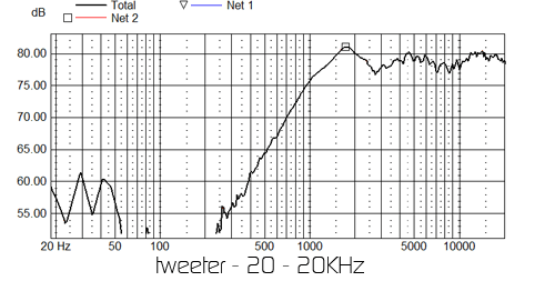
Things are in pretty good shape from 3,000 Hz on up. But notice the dip
and peak below that point. All tweeters will have a similar profile in
this box. As the sound waves at those frequencies reach the edges of the
baffle, some will be reflected back and either cancel or augment new
waves just leaving the tweeter. These “diffraction effects” are also
evident in the slight dips much further up. But what’s important is that
even excellent tweeters will not have a smooth natural roll off in the types
of cabinet baffles that are normally used. And that’s another challenge for the crossover.
running with no crossover
Now let’s make a complete mess and run both drivers with the test signal
at the same time. (The black line is the total output, the blue is the woofer alone, and the red is the tweeter alone.)
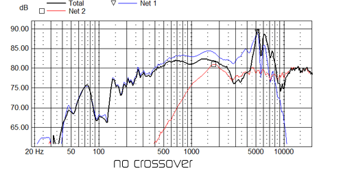
This is not something you want to listen to. (And it will also void the
warranty on the tweeter.) There is way too much output in the midrange and treble compared with the bass range. The tweeter will be distorting badly below 2000Hz, and you will hear the woofer’s breakup peaks at full cry.
what now?
Hopefully I’ve established that some means must be found to keep the
drivers out of each other’s way, and to restrict their operation to the
frequency range they handle best. This can be accomplished through
appropriate use of inductors (which are just tightly coiled wires of
various lengths and gauges-hence the nick name “coil”), capacitors, and
resistors.
If you connect an inductor between the amplifier and the positive terminal of the woofer, it will roll the woofer off at the top at a rate of roughly 6 dB an octave starting at a point determined by the value of the inductor. If you
connect a capacitor to the tweeter positive terminal, it will roll the tweeter off at the bottom at roughly 6 dB per octave. If you add a capacitor to the woofer circuit after the inductor, but wire it to ground instead of in series, you will get roughly a 12 dB roll off per octave. If you add another inductor in series as the 3rd component, you will add another 6 dB of attenuation per octave. Finally, if you add a second capacitor to ground, you add yet another 6 dB of roll-off, for a total of 24 dB per octave.
This kind of roll-off is called a “4th order slope,” and the 6dB slope from the single inductor is called a “1st order slope.” (No extra credit will be
given for telling me what a 2nd or 3rd order slope is.) If you replace the
word “inductor” with “capacitor” and vice versa, you get the same
results for a tweeter at the bottom of its range. Warning! These
roll-off rates don’t really work in practice, as we will illustrate, but
I just wanted you to see where the nomenclature comes from, and what the
basic building blocks of crossovers are.
At this point, let me introduce one of those religions I alluded to at
the beginning.
“Less is more. The best crossover is a simple first order
design that uses one inductor in series with the woofer and one
capacitor in line with the tweeter.”
If I wanted to thoroughly confuse you, I could elaborate on the “phase coherence” and soundstage advantages that these advocates claim. But for this blog, just accept that this approach to crossover design is touted over and over again. And it’s actually the type of crossover that many mass merchandise speakers employ-the ubiquitous “cap and a coil.”
a minimalist crossover
OK, so let’s see what happens when we use this minimalist approach to a crossover with the drivers I’ve discussed. Because the slopes will be so gentle, the tweeter will have to start rolling off fairly early (at a higher frequency)to avoid handling lots of output below 2,000 Hz. This in turn will require a relatively high crossover point for the woofer.
�
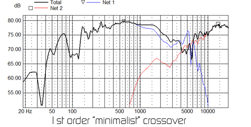
The crossover point–where the slopes from the woofer and tweeter intersect-is about 5,500 Hz. It’s evident from the big dip in the response that the woofer and tweeter are interfering with each other over the crossover region.
That’s because they are out of phase with each other in that region because of the roll-off rates that result from our simple crossover. The explanation for this is way too complex and difficult to attempt here. But a successful crossover design must take such phase issues into account. Further, the sound will actually be worse than the graph looks. Because we haven’t done much of anything to suppress the resonant break-up of the woofer, you will hear it ringing like a bell.
Also notice that our “first order, 6 dB slope per octave” crossover hasn’t produced anything like smooth first-order slopes in terms of the actual output of the drivers. In particular, the woofer roll-off above the crossover point is much steeper than 6 dB per octave, because the inherent response of the driver is dropping off rapidly without any help from the crossover. So, in addition to a ragged frequency response, our “first order” cap and coil won’t provide the slopes necessary to achieve the phase coherence benefits that are claimed for that approach.
4th order alternative
What to do? We have to cross the woofer lower to get the breakup region suppressed by at least 20 dB. And that means we’ll have to resort to a steeper slope for the tweeter to avoid overtaxing it at the low end. And if we want the two drivers to sum properly to produce a smooth response curve, we’ll have to pay close attention to the phase relationships between drivers in the crossover region, where they overlap the most.
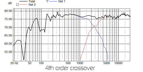
One of the most effective and popular ways to manage all this is to use a 4th order “Linkwitz-Riley” crossover design. We can skip the details, but with this approach the tweeter and woofer are exactly in phase where they meet (although they will be one cycle apart--that's a subject for a different blog), and roll off at 24 db per octave. Let’s try that with our two drivers. I'm going to cross the woofer and tweeter at about 2400 Hz, which saves the tweeter from any melt-downs, and keeps the woofer in the range where it is most linear and also has reasonably wide dispersion. Fortunately, I won’t have to use as many crossover components as you might think from my earlier description of a 4th order crossover, because I can take advantage of the natural roll-offs of the drivers to reach the desired slopes. Here’s the result:
that's better
That looks a lot better, and it definitely sounds better--I've listened to both. Notice that the break-up region of the woofer is now about 30 dB lower in output than the overall response of the speaker, and the tweeter is out of trouble at its low end.* To see whether the woofer and tweeter really are in phase where they cross, I can use my magic software to reverse the wiring to the tweeter, and that should produce a deep "null" where the drivers cancel each other out because they are now exactly out of phase.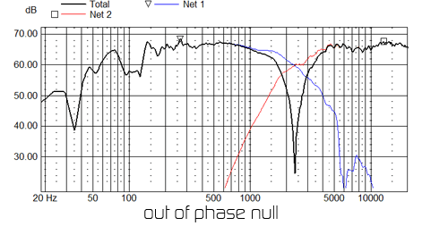
The null is about 40 dB deep, which is about as good as you can do.
I've glossed over or ignored a lot of important topics--like impedance, acoustic centers, lobing, power response, and the ins and outs of phase. Oh—and I’ve only discussed 2-way crossovers. But hopefully it will be a little clearer to you why crossovers are so important, and why I spend so much time designing them.
*For reasons that will have to be the subject of a different blog, the roll-off of the woofer is actually less than 24 dB per octave.