09
Apr
2013

One of the most misunderstood topics in audio is the subject of diffraction. Diffraction, acoustic phase, and how listening rooms impact our reproduction of sound, based on what I see posted in many discussions on the internet, are subjects of much confusion. In this article I will attempt to clear some of the fog on the topic of cabinet diffraction, and hopefully, present it in such a way as to make it much easier to understand.
What is Diffraction?
Diffraction is the name given to the “bending” of waves (distortion of wavefronts) produced when they interact with objects that are comparable to a wavelength in size. This is in contrast to the much simpler phenomenon of reflection, which leaves the waveform shape intact. Both partial reflection and diffraction occur when sound waves encounter an obstacle in its path.
The description is same whether we are discussing light, sound, or waves in the water. All of these diffract in ways that are predictable and consistent. In fact, most of the early work in diffraction came from the field of Optics, as far back as before Isaac Newton, and as a result we will sometimes use terms like “illuminating” the edge, and a “shadow zone” even when discussing the diffraction of sound waves.
In order to get a good visual image of wave diffraction let’s picture a pond of still water. In this pond there is a small branch sticking out of the water, and several feet away there is a frog sitting on a rock. Suddenly the frog leaps into the water. This sets off a waveform moving outward from the frog’s entry point in concentric circles, in all directions (360 degrees). After a few seconds of travel the leading edge of the waveform encounters the branch sticking out of the water. The wave diffracts on this obstacle, and we see a new set of waves moving outward from the branch in all directions, including a portion of the wave moving directly back towards its origin where the frog went in. There is both reflection and diffraction of wavefronts in this example.
These two waveforms will now interact either constructively, by adding in amplitude, or destructively, by canceling each other, depending on their relative phase – which is their up and down motion at the point where they intersect. Although this sounds somewhat complicated, I bet most of you had no trouble picturing this scene and following what I described. And, this is precisely the same thing that happens with sound propagating in the air. When sound is propagating from a loudspeaker it diffracts when it encounters the edges of the cabinet and other obstacles nearby.
Baffle Step is Diffraction?
Yes, sort of, but first we need to understand a few fundamental principles of acoustics before this will make sense. First of all, we must understand that sound is pressure, or more precisely, it is the propagation of pressure waves in air. That’s why it is referred to as SPL (Sound Pressure Level). Second, we need to understand that this pressure is pushing a waveform that is expanding to fill the space around it in a spherical manner. In other words, it is expanding in all directions equally – just like the pressure inside a balloon is pushing outward in all directions equally. And third, we need to understand that the acoustic effects of diffraction are always directly related to the ratio of distance versus the wavelength of sound at a given frequency.
Wavelengths are inversely proportional to frequency. Low frequencies have very long wavelengths and higher frequencies have much shorter wavelengths. Therefore, for a given edge distance or baffle width the effect will be different based on the frequency discussed and its wavelength. An obstacle must be “acoustically large” before full diffraction will occur. An obstacle is “acoustically large” when its dimensions are greater than one-half of a wavelength at a given frequency, at this point there will be full diffraction of the waveform, or the obstacle will fully alter the direction and behavior of the wave. As an object gets progressively smaller than one-half of a wavelength it will have progressively less effect on the wave. Once it is around one-tenth of a wavelength in size it will be small enough acoustically to be essentially invisible to the waveform at those frequencies. Technically, the effects of diffraction asymptotically reach 0 dB only at 0Hz, but for most of this range the effects are only fractions of a decibel until the obstacle begins to become acoustically large.
Speaker drivers are usually rated with what is called “half-space sensitivity” (sometimes called 2Pi or hemispherical space – 2Pi is a geometrical way of describing half of a sphere, whereas 4Pi describes a full sphere). Because of this, we will usually describe baffle step as a loss due to low frequencies “wrapping” around the baffle into “full-space” (4Pi or spherical space) due to their wavelengths being so much longer than the width of the baffle. This description can be correct depending upon your perspective; however it really doesn’t accurately describe the phenomena in a way that allows you to see how baffle step and diffraction are tied together.
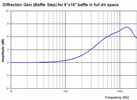
To be technically accurate we need to picture it in this way: When a loudspeaker produces a sound, this sound is in the form of a pressure wave trying to expand equally in all directions spherically (like the balloon analogy). The first obstacle that this wave encounters is the baffle face itself. For higher frequencies with shorter wavelengths where the baffle is acoustically large, the baffle causes a doubling of axial pressure into the forward hemisphere (since the pressure can’t expand spherically), much like a perfect reflector. This doubling of acoustic pressure produces a +6dB gain on axis in the forward hemisphere. A baffle with a width of about 9” would correspond to one wavelength at about 1500Hz, this +6dB gain would then be seen at frequencies above 750Hz (that half-wavelength rule. Of course, a taller height dimension pushes this a little lower in frequency in real life). At lower frequencies this gain is progressively less, dropping to near 1 dB at about one-tenth of 1500Hz, or 150 Hz (again, the taller height will push this a little lower, but you get the idea).
At very low frequencies, below 100Hz in our example, the cabinet baffle is “acoustically small enough” to become “invisible” to these longer wavelengths. As a result they have very little effect on the waveform at all; the wave is able to expand reasonably unhindered as a sphere, and there is almost no gain or ripples in the waveform due to diffraction. At higher frequencies above 750Hz the baffle is “acoustically large enough” to fully obstruct spherical expansion of the waveform, acoustic pressure is doubled, and there is a +6dB gain in the response on the forward axis. Of course, what is given up in exchange is that there is very little energy at these higher frequencies behind the speaker. There is no gain in energy here, only a redirection. In between these two frequencies there is a transition as the baffle progressively diffracts the spherical propagation of the waveform. This produces a smooth rise from 0 dB to +6dB, and this is actually what is happening in what we call baffle step. It is diffraction; or more precisely, it is moving from a state of no diffraction into full diffraction as the baffle becomes acoustically larger with increasing frequency. Diffraction is really computed from the perspective of a full 4pi – spherical space. Below what we call the baffle step frequency there is very, very little diffraction at all. The wavelengths are acoustically too large to diffract on the baffle, so the baffle is essentially invisible to the long sound waves at these frequencies. However, the baffle step gain – the rising of the step – IS diffraction.
So What About Edge Diffraction – What’s Happening Here?
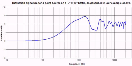
OK, here’s the anatomy of a diffraction signature. Continuing with our example, let’s define our baffle as a 9″ wide by 16″ tall mini-speaker with the driver mounted centered on the baffle and only 4″ from the top (or bottom). For the sake of our discussion we will treat this driver as a point source. That places this point source at 4.5″ from both sides and 4″ from the top. This is actually a fairly common location for tweeters, and small woofers may be similarly placed at the other end.
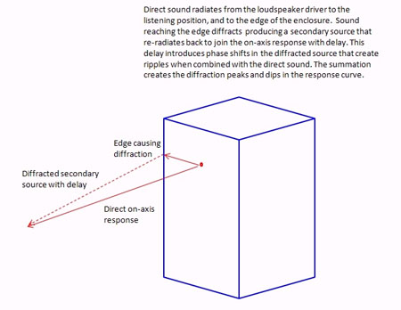
Now, to figure the edge diffraction we need to picture the point source as a point with rays going off in all directions to the baffle edges. The point source is like the point where our frog entered the water. The rays are lines (radii) following those concentric circles moving outward in our pond. Each ray will have a specific distance before it encounters the cabinet edge and diffracts. When it diffracts, like the log in the water, the edge becomes a secondary sound source and some of the acoustic energy is reflected back toward the listener or microphone to combine with the original source with delay. How much delay depends on the frequency and the distance of the ray. Picture a triangle: One side of the triangle is the distance from the driver to the listener. The short side of the triangle is the distance from the driver to the edge of the cabinet. And the hypotenuse of the triangle is diffracted secondary waveform. Because it is longer than the direct path there will be delay and some phase shifts – Just like the phase shifts of our waves in the water combining.
Unfortunately, in our example the point source is very close to the same distance from three different edges (I did this on purpose for our example). It is actually fairly complex because the ray distances will vary continuously as you move around the baffle, encountering edges at the sides, top, bottom, and corners, but a large percentage of them will fall in the range from 4-5.5″ due to the driver placement. This means that the influence of this distance will be much greater in the final result than many other ray distances will be. This distance corresponds to a frequency range of 2.4 kHz – 3.4 kHz with a center point at 3 kHz. When the waveform of sound from the driver moves across the baffle it encounters a sudden discontinuity when it reaches the edge of the enclosure. Frequencies in this range will reach these edges, diffract, and reflect back to the listener delayed out of phase since it is exactly one wavelength. The level will be reduced so there won’t be complete cancellation, but there will be a notch in the diffraction signature centered around 3 kHz. This notch is typical in many mini-monitors due to this distance and the associated diffraction.
On the other hand, the frequencies whose wavelengths are twice this distance, so that a half-wavelength is reaching these edges will diffract to combine with the original source in-phase, but at a lower level. These frequencies will combine constructively and produce an additional gain that could reach +3 dB above the already +6dB, however, since the frequencies will be spread somewhat the gain will be slightly less than the full 9 dB peak. This peak will be twice as wide as the notch described above, and at half the frequency, so it will peak at about 1500 Hz. By the way, due to this peak, and typical crossover points for midwoofers, baffle step could actually appear to be more than the normally discussed 6dB once this hump of +2 to +3 dB is taken into consideration.
Now, we also have some longer rays going to the bottom edge of our enclosure doing the same, these are in the 12-14″ range. This corresponds to a wavelength of just over 1000Hz, so there will be a little down-ripple in the response at this frequency, and a half-wavelength of around 500Hz, so there will be a little up-ripple here due to these distances as well.
So now we have defined the typical baffle step, the peak, and the notch. At frequencies higher than this notch it is all the same mechanism that we have already discussed and applied – only the wavelengths get shorter and the phase of the diffracted sound becomes more randomized, and the ripples get narrower and shorter in amplitude. Diffraction is a form of linear distortion, because it affects the frequency response on a given axis and has a minimum phase relationship, meaning the phase is directly related to the frequency response.
I hope this explains it reasonably well. It is all about ray length, driver location, and the wavelength of the sound reaching the edge and then recombining with the original source either in-phase or some degree out of phase.
How Do You Control Diffraction?
Well, the best way would be to eliminate it, but that would involve mounting the drivers on an infinite baffle, or flush in a wall, and that doesn’t work out very well for most people. For speaker drivers mounted in a typical cabinet you can not eliminate the effects of diffraction from the cabinet, but there are several techniques that compensate for, or reduce the impact these effects significantly.
First, the most obvious diffraction effect for the typical small stand mounted monitor or the tall narrow tower type of speaker is the “baffle step” in the response that was discussed above. Fortunately, this step is fairly smooth and easy to measure on the design axis, because of this it can easily be compensated for in the crossover design. The negative side of this compensation is an apparent reduction in loudspeaker sensitivity of 6dB. The truth is that the original driver sensitivity was rated based on half-space (hemispherical) radiation, and we have adjusted everything to a flat response based on the full-space (Spherical) radiation of lower frequencies. The loss of sensitivity is traded off for flat on-axis frequency response. This trade-off is worth the drop in sensitivity. If you have listened to speakers that do not compensate for this step, the sound can be very thin in the lower midrange and bass, leaving you with a forward, bright, irritating sound.
This leaves us with cabinet edge diffraction. Several different techniques have been employed over the years to reduce the effects of edge diffraction. One of the most effective is the use of a thick felt whose tangle can effectively absorb and diffuse the sound waveform moving along the baffle before it can encounter the edge and then diffract and recombine as described above, creating irregularities in the frequency response. Despite its effectiveness few commercial loudspeakers use felt, mostly for cosmetic reasons, but there are some notable exceptions that have been very successful. Most loudspeaker purchasers though, weigh the appearance of the speaker with the sound presentation when making their selection. As humans, we are strongly visually driven, even when looking for good sound.
Fortunately, there are some techniques that work well in reducing edge diffraction effects and improve the appearance of the loudspeaker at the same time. One thing that needs to be done is to recess each loudspeaker driver so its faceplate or frame is flush with the baffle. It may not seem like it matters at first, but for surface mounted drivers the tweeter’s response will actually be impacted by the diffraction from its own faceplate edges as well as from the frame of the woofer mounted nearby. Flush mounting is an important feature that both aids in diffraction control and improves the appearance at the same time.
Sometimes you will see a tweeter offset from the centerline of a baffle. This asymmetric mounting is also a diffraction control technique. By offsetting the tweeter, the distance from the center of the tweeter to the left edge and the right edge are different distances. This means that the frequencies whose wavelengths correspond to these distances are different too. By offsetting these frequencies you can sometimes smooth the on-axis diffraction signature because the distances to each edge will produce ripples at different frequencies. If carefully designed, these can combine to smooth the response. When using this technique it is important to note that the diffraction signature is asymmetrical too and there is a greater difference in the response whether you move off-axis to the left or to the right compared to a centered tweeter that is symmetrical. Similar to offsetting the tweeter is the technique of “toeing-in” the loudspeaker so you are not directly on-axis. This has a similar effect to offsetting the driver because your off-axis position changes the geometry of how the sound recombines after diffracting off of each edge.
Another technique is to add a large radius to the edges of the cabinet. Many manufacturers will stick with a standard rectangular box with square edges as a cost savings, but the frequency response will have much more variation than it would have if the cabinet was rounded on the edges with a fairly large radius. It is costly to make baffles that are rounded or curved, but the impact on frequency response can be dramatic. The larger the radius or curve usually the better the diffraction control, and the smoother the frequency response will be. Here’s why –
When a waveform is moving across the baffle and encounters a sharp edge with a sudden discontinuity of 90 degrees, there is a very sudden change in the propagation of the wave. The sharp corner acts like an obstacle changing the direction of the wave; the wave diffracts and the edge becomes a secondary source, reradiating sound back towards the original wave, as we have discussed. When a large radius is used the waveform moves across the baffle and tends to follow the radius as it curves away from the front. There is no sudden discontinuity in its path. This does not mean that there is no diffraction, but the larger the radius the lower in frequency the disturbances lie. The large rounded radius accomplishes two things that benefit our diffraction issue: First, the smoother path around the corner of the baffle reduces the amplitude of the disturbance at specific frequencies, thus reducing the overall impact on the frequency response. This occurs because the rounded edge is seen as a “fuzzier” less defined edge, and this spreads the affected frequencies over a wider range than a sharp edge does. Second, as the wave does begin to diffract on this radius part of the energy is redirected at different angles away from the baffle, so less diffracted e